|
FreeCore Function #12:
MII Management Interface Controller
Module name: mii
Current release: version 1.0, August 20, 1997
Contributed by: Woody Johnson woodyj@dacmail.net
Introduction
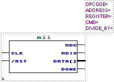
Shown below is the schematic representation of the module:

This is a design that can be used to read or write a register value as defined by the
IEEE 802.3 MII Management Interface. For instance - all 100Mb Ethernet PHYs with an MII
interface have a serial management port with several registers that can be accessed by
this design.
Theory of Operation
The design operates immediately upon negation of the input reset signal and proceeds to
commence a one time read or write command sequence as determined by module parameters.
Module Parameters
| PARAMETERS |
| OPCODE |
"READ" or "WRITE". |
| ADDRESS |
0-31. This value selects the PHY, or destination of the access. |
| REGISTER |
0-31. This value selects the register to access. |
| CMD |
0-FFFF. This is the value written to the register (if "WRITE" opcode
selected). |
| DIVIDE_BY |
>0. Clk input frequency is divided by 2^DIVIDE_BY to generate MDC clock
frequency. This should be chosen to result in a frequency <= 2.5MHz. |
| INPUT PORTS |
| Clk |
System clock input. More than 75MHz is possible using a MAX7K-15 device. |
| /Rst |
Asynchronous low-active reset. |
| OUTPUT PORTS |
| MDC |
Management Data Clock. |
| MDIO |
Management Data Input/Output. |
| Data[15..0] |
Data value read from or written to device. |
Enjoy!
返回
|